Engineering Scope
Installation Snapshot: Aligning duplex and triplex sprockets
Align every tooth row of a multi-strand sprocket by establishing shaft parallelism, axial row position, low runout, and equal chain seating so all strands share load. This article concentrates on duplex sprocket alignment, triplex sprocket alignment, multi-strand chain, row alignment, shaft parallelism, and chain tracking as field-verifiable decision inputs.
For aligning duplex and triplex sprockets, keep chain engagement, shaft mounting, operating duty, and maintainability in the same decision record; use the current drawing whenever an exact limit is model-specific.
Field Reference
- Chain/tooth interface
- Confirm duplex sprocket alignment, triplex sprocket alignment, and the mating chain dimensions before changing hardware.
- Shaft/hub interface
- Record multi-strand chain and mounting details that control concentricity, axial position, or load transfer.
- Operating duty
- Document speed, load, shock, starts/reversals, contamination, washdown, and maintenance access relevant to aligning duplex and triplex sprockets.
- Verification record
- For aligning duplex and triplex sprockets, keep measured values, nominal drawing values, wear observations, and the final replacement requirement distinct in the service record.
Decision Principle
Release aligning duplex and triplex sprockets from measured interfaces, not appearance.
For aligning duplex and triplex sprockets, check the chain interface, shaft connection, duty, and installed geometry as separate acceptance items, then reconcile them in the final specification.
Installation Sequence
- 1. Check shafts. Verify bearing condition, shaft parallelism, end float, and the absence of bent or fretted seats. Record the result against row alignment so the next step starts from measured evidence.
- 2. Measure sprocket row spacing. Confirm the tooth-row center spacing matches the chain construction before using the sprocket as an alignment reference. Use the current machine drawing when shaft parallelism is model-specific, and keep the measured value in the service record.
- 3. Set axial position. Align corresponding tooth rows with a straightedge, laser, or dimensional datum across the two shafts. Before moving on, confirm that chain tracking agrees with the mating chain or shaft interface relevant to this step.
- 4. Rotate and recheck. Measure at multiple angular positions to distinguish fixed axial offset from sprocket wobble or shaft eccentricity. Record the result against duplex sprocket alignment so the next step starts from measured evidence.
- 5. Install the chain without forcing it sideways. Fit the multi-strand chain, set the specified slack, and verify all rows seat freely without prying or side pressure. Use the current machine drawing when triplex sprocket alignment is model-specific, and keep the measured value in the service record.
- 6. Inspect load sharing. During startup, look for one-sided polishing, uneven slack, temperature differences, or noise that suggests one strand is carrying more load. Before moving on, confirm that multi-strand chain agrees with the mating chain or shaft interface relevant to this step.
For aligning duplex and triplex sprockets, cross-check adjacent drive interfaces with industrial chain drive alignment before releasing the installation or replacement record.
1. Wider drives magnify small angular errors
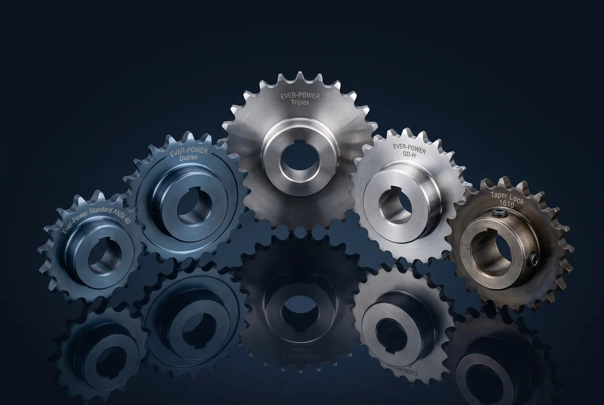
With two or three tooth rows, a shaft-angle error creates different axial displacement across the chain width. One strand can rub or carry load before the others show obvious distress. For aligning duplex and triplex sprockets, use duplex sprocket alignment as the primary field reference and compare it with multi-strand chain; resolve any disagreement before releasing the sprocket specification. For component context, review duplex and triplex sprockets when the linked product family is relevant to the same chain-drive interface.
Use the wear evidence to test wider drives magnify small angular errors: asymmetric polishing, fretting, root impact, or chain climbing should lead to a measurable correction rather than a like-for-like replacement.
2. Corresponding rows must be coplanar
Align row one to row one, row two to row two, and so on. Overall sprocket face alignment is not enough if tooth-row spacing or hub machining is wrong. The practical check for corresponding rows must be coplanar is to connect the observed condition to triplex sprocket alignment, then confirm that row alignment does not introduce a second compatibility limit.
For procurement, express corresponding rows must be coplanar as verifiable data: chain standard, measured dimension, drawing reference, material condition, or operating requirement. Do not specify only ‘same as old.’
3. Runout can make alignment appear to change
Check at several angular positions. If the measured axial relationship changes with rotation, face wobble or shaft runout is present and should be corrected before setting the chain line. Record the evidence for runout can make alignment appear to change beside the measured multi-strand chain. If shaft parallelism is size- or supplier-dependent, carry the drawing reference into the purchase record. For component context, review multi-strand roller chains when the linked product family is relevant to the same chain-drive interface.
For commissioning, define how runout can make alignment appear to change will be checked after installation: chain seating, runout, shaft clearance, tooth-side contact, rpm, or loaded inspection as applicable.
4. Chain condition affects load sharing
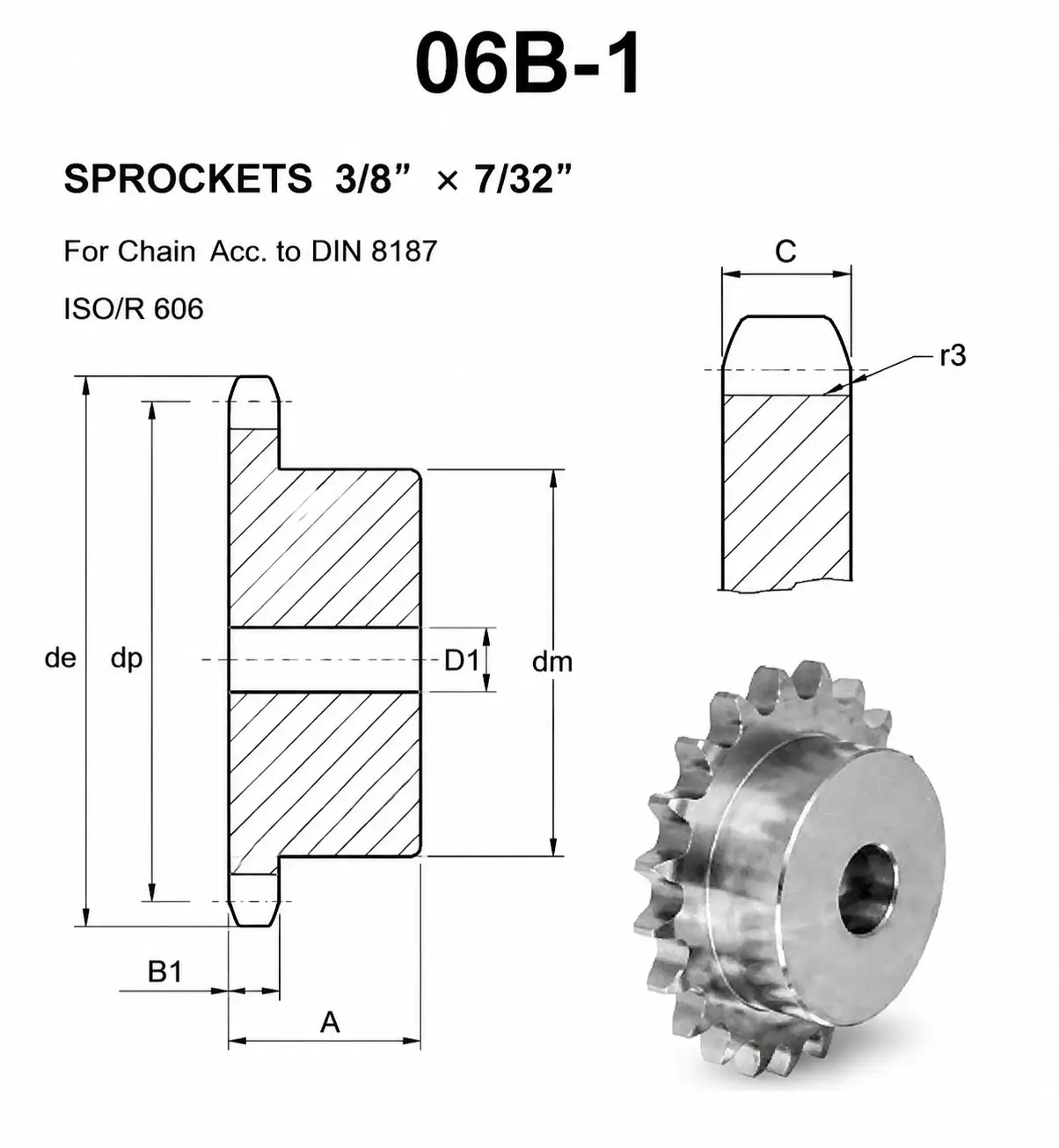
Different elongation or stiff joints between strands can prevent equal loading even when the sprockets are geometrically aligned. Multi-strand chain should be treated as one matched assembly. Treat chain condition affects load sharing as a pass/fail interface: document row alignment, inspect the mating component, and use chain tracking to confirm the final operating fit.
Verification for aligning duplex and triplex sprockets: compare the field condition with nominal data and treat any difference that changes roller seating, shaft support, or service access as a release criterion.
5. Shaft and bearing stiffness matter
A wide sprocket under load can deflect the shaft or bearings enough to disturb alignment. Static alignment is necessary but should be verified under representative operating load where possible. A useful field note for aligning duplex and triplex sprockets pairs shaft parallelism with duplex sprocket alignment. That keeps the decision tied to the actual chain drive rather than a visual match.
Use the wear evidence to test shaft and bearing stiffness matter: asymmetric polishing, fretting, root impact, or chain climbing should lead to a measurable correction rather than a like-for-like replacement.
Installation Check Matrix
| Factor | What to verify | Release logic |
|---|---|---|
| Wider drives magnify small angular errors | With two or three tooth rows, a shaft-angle error creates different axial displacement across the chain width | Correct the system cause linked to wider drives magnify small angular errors before fitting new hardware. |
| Corresponding rows must be coplanar | Align row one to row one, row two to row two, and so on | Accept corresponding rows must be coplanar when field evidence matches the controlled requirement. |
| Runout can make alignment appear to change | Check at several angular positions | Reconstruct nominal runout can make alignment appear to change if wear has obscured the original geometry. |
| Chain condition affects load sharing | Different elongation or stiff joints between strands can prevent equal loading even when the sprockets are geometrically aligned | Use the current supplier or machine limit for model-specific chain condition affects load sharing. |
| Shaft and bearing stiffness matter | A wide sprocket under load can deflect the shaft or bearings enough to disturb alignment | Record shaft and bearing stiffness matter as a release check before installation or restart. |
| Use measured machine data and the current chain/sprocket drawing for final acceptance; model-specific limits are not interchangeable. | ||
Startup Verification
Avoid 01
Aligning only the outer sprocket faces. Document the corrective requirement specifically for aligning duplex and triplex sprockets before the part is released.
Avoid 02
Assuming row spacing is correct because both parts are labeled duplex. Document the corrective requirement specifically for aligning duplex and triplex sprockets before the part is released.
Avoid 03
Using chain tension to pull misaligned rows together. Document the corrective requirement specifically for aligning duplex and triplex sprockets before the part is released.
Avoid 04
Ignoring bearing or shaft deflection in a wide high-load drive. Document the corrective requirement specifically for aligning duplex and triplex sprockets before the part is released.
Configuration cross-check: use this multi-strand roller chain reference only to compare common construction terminology for aligning duplex and triplex sprockets; release the part from the actual chain, shaft, and controlled drawing.
FAQ: Aligning duplex and triplex sprockets — practical engineering questions
How do I align duplex sprockets?
Make the shafts parallel, then align each corresponding tooth row in the same plane. Check more than one rotational position to detect wobble before installing the chain.
Why does one row of a triplex chain wear faster?
Possible causes include row misalignment, incorrect sprocket spacing, shaft deflection, unequal chain elongation, runout, or contamination concentrated on one side.
Can I use a straightedge to align multi-strand sprockets?
Yes when the referenced faces are machined and known to represent the tooth planes. A laser or dimensional datum is useful for longer center distances.
Do duplex sprockets need the same axial location on both shafts?
Their corresponding tooth rows must be coplanar. Hub faces can sit at different axial positions if the tooth planes still align correctly.
Should I align sprockets before or after final bushing tightening?
Set preliminary position first, complete the mounting procedure, then perform the final alignment and runout check because taper seating can shift the sprocket.
What measurements should I record for a multi-strand alignment problem?
Record shaft parallelism, tooth-row center spacing, axial row offsets, radial and axial runout, chain elongation, slack, bearing movement, and wear on each tooth row.