Engineering Scope
Diagnostic Snapshot: Sprocket teeth wearing on one side
Use asymmetric side wear as evidence of chain-line error, shaft nonparallelism, sprocket wobble, frame movement, or guide interference, then measure rather than simply moving the sprocket by eye. This article concentrates on sprocket side wear, chain misalignment, shaft parallelism, sprocket coplanarity, side plate rubbing, and tooth face wear as field-verifiable decision inputs.
For sprocket teeth wearing on one side, keep chain engagement, shaft mounting, operating duty, and maintainability in the same decision record; use the current drawing whenever an exact limit is model-specific.
Field Reference
- Chain/tooth interface
- Confirm sprocket side wear, chain misalignment, and the mating chain dimensions before changing hardware.
- Shaft/hub interface
- Record shaft parallelism and mounting details that control concentricity, axial position, or load transfer.
- Operating duty
- Document speed, load, shock, starts/reversals, contamination, washdown, and maintenance access relevant to sprocket teeth wearing on one side.
- Verification record
- For sprocket teeth wearing on one side, keep measured values, nominal drawing values, wear observations, and the final replacement requirement distinct in the service record.
Decision Principle
Release sprocket teeth wearing on one side from measured interfaces, not appearance.
For sprocket teeth wearing on one side, check the chain interface, shaft connection, duty, and installed geometry as separate acceptance items, then reconcile them in the final specification.
1. Side polishing points to axial force
Rollers should carry load on the tooth profile without sustained rubbing of chain plates against one tooth side. Bright side bands suggest the chain is being steered laterally. For sprocket teeth wearing on one side, use sprocket side wear as the primary field reference and compare it with shaft parallelism; resolve any disagreement before releasing the sprocket specification. For component context, review sprocket alignment and wear when the linked product family is relevant to the same chain-drive interface.
For procurement, express side polishing points to axial force as verifiable data: chain standard, measured dimension, drawing reference, material condition, or operating requirement. Do not specify only ‘same as old.’
2. Shaft angle and sprocket offset create different patterns
Parallel shafts with axial offset can produce fairly consistent side contact; nonparallel shafts can make tracking change across the span or with shaft position. The practical check for shaft angle and sprocket offset create different patterns is to connect the observed condition to chain misalignment, then confirm that sprocket coplanarity does not introduce a second compatibility limit.
For commissioning, define how shaft angle and sprocket offset create different patterns will be checked after installation: chain seating, runout, shaft clearance, tooth-side contact, rpm, or loaded inspection as applicable.
3. Face wobble creates cyclic side contact
A sprocket with axial runout moves the tooth plane from side to side once per revolution. The chain may alternately rub and release, creating periodic noise and polished arcs. Record the evidence for face wobble creates cyclic side contact beside the measured shaft parallelism. If side plate rubbing is size- or supplier-dependent, carry the drawing reference into the purchase record. For component context, review roller chain alignment when the linked product family is relevant to the same chain-drive interface.
Verification for sprocket teeth wearing on one side: compare the field condition with nominal data and treat any difference that changes roller seating, shaft support, or service access as a release criterion.
4. Guides and structure can push the chain sideways
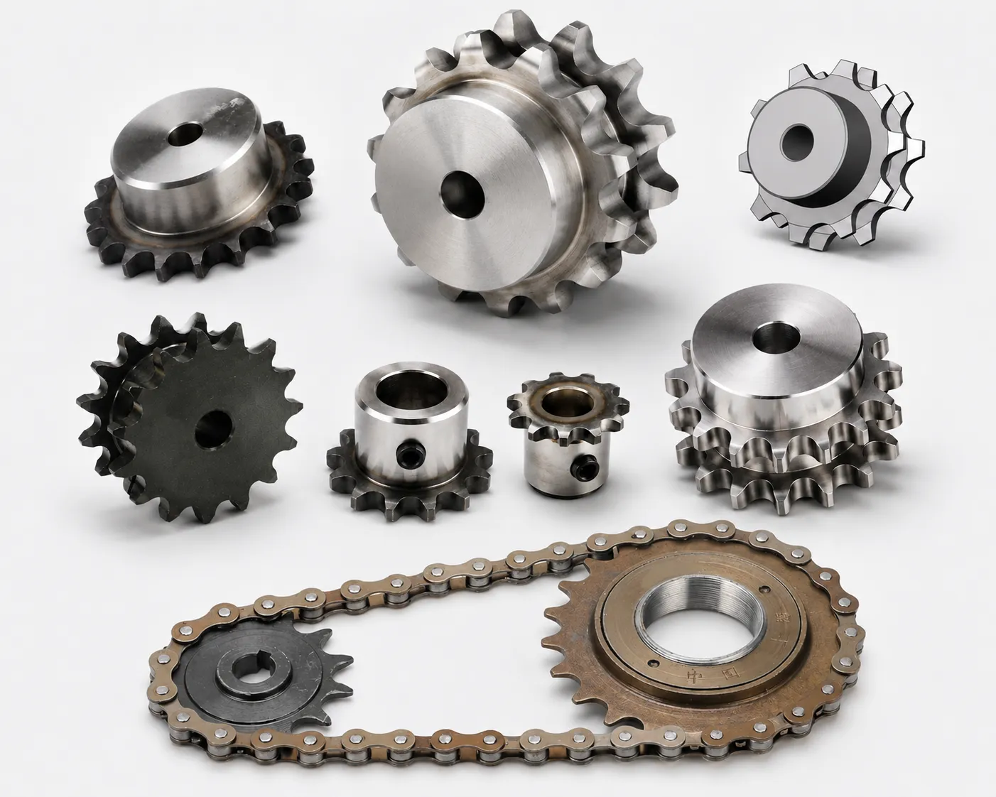
Conveyor rails, guards, tensioners, or bent brackets can force a correctly aligned sprocket drive out of plane. Trace the full chain path rather than measuring only the sprocket pair. Treat guides and structure can push the chain sideways as a pass/fail interface: document sprocket coplanarity, inspect the mating component, and use tooth face wear to confirm the final operating fit.
Use the wear evidence to test guides and structure can push the chain sideways: asymmetric polishing, fretting, root impact, or chain climbing should lead to a measurable correction rather than a like-for-like replacement.
5. Wear can continue after visual realignment
If tooth sides or chain plates have already worn significantly, the geometry and clearance may remain abnormal. Decide whether the damaged parts need replacement after correcting alignment. A useful field note for sprocket teeth wearing on one side pairs side plate rubbing with sprocket side wear. That keeps the decision tied to the actual chain drive rather than a visual match.
For procurement, express wear can continue after visual realignment as verifiable data: chain standard, measured dimension, drawing reference, material condition, or operating requirement. Do not specify only ‘same as old.’
Symptom-to-Action Matrix
| Factor | What to verify | Release logic |
|---|---|---|
| Side polishing points to axial force | Rollers should carry load on the tooth profile without sustained rubbing of chain plates against one tooth side | Correct the system cause linked to side polishing points to axial force before fitting new hardware. |
| Shaft angle and sprocket offset create different patterns | Parallel shafts with axial offset can produce fairly consistent side contact; nonparallel shafts can make tracking change across the span or with shaft position | Accept shaft angle and sprocket offset create different patterns when field evidence matches the controlled requirement. |
| Face wobble creates cyclic side contact | A sprocket with axial runout moves the tooth plane from side to side once per revolution | Reconstruct nominal face wobble creates cyclic side contact if wear has obscured the original geometry. |
| Guides and structure can push the chain sideways | Conveyor rails, guards, tensioners, or bent brackets can force a correctly aligned sprocket drive out of plane | Use the current supplier or machine limit for model-specific guides and structure can push the chain sideways. |
| Wear can continue after visual realignment | If tooth sides or chain plates have already worn significantly, the geometry and clearance may remain abnormal | Record wear can continue after visual realignment as a release check before installation or restart. |
| Use measured machine data and the current chain/sprocket drawing for final acceptance; model-specific limits are not interchangeable. | ||
Inspection Sequence
- 1. Map the wear side. Record which sprocket, which tooth side, and which chain-plate edge shows polishing or scoring. Photograph the setup when useful and identify the reference surfaces used to establish sprocket coplanarity.
- 2. Check shaft parallelism. Measure the shaft or bearing datums rather than assuming the frame faces are accurate references. If the observation changes side plate rubbing, stop and update the replacement specification before continuing.
- 3. Check sprocket coplanarity. Use a straightedge, laser, or measured tooth-plane datums and verify at multiple rotational positions. Repeat or rotate the check when wear could bias tooth face wear; the goal is nominal geometry, not one convenient reading.
- 4. Check axial runout. Indicate a machined sprocket face and compare the side movement with the machine or sprocket limit. Photograph the setup when useful and identify the reference surfaces used to establish sprocket side wear.
- 5. Trace guides and tensioners. Inspect every component that touches or constrains the chain for asymmetric wear or displacement. If the observation changes chain misalignment, stop and update the replacement specification before continuing.
- 6. Correct and monitor. Restore alignment, replace severely worn parts, set slack, lubricate, and mark tooth sides so new rubbing can be detected after restart. Repeat or rotate the check when wear could bias shaft parallelism; the goal is nominal geometry, not one convenient reading.
For sprocket teeth wearing on one side, cross-check adjacent drive interfaces with industrial power transmission maintenance before releasing the installation or replacement record.
Prevention Checks
Avoid 01
Moving one sprocket until the chain looks straight without checking shaft angle. Document the corrective requirement specifically for sprocket teeth wearing on one side before the part is released.
Avoid 02
Ignoring axial runout because average alignment is correct. Document the corrective requirement specifically for sprocket teeth wearing on one side before the part is released.
Avoid 03
Treating polished tooth sides as normal wear. Document the corrective requirement specifically for sprocket teeth wearing on one side before the part is released.
Avoid 04
Correcting sprockets while a bent guide continues to steer the chain. Document the corrective requirement specifically for sprocket teeth wearing on one side before the part is released.
Configuration cross-check: use this chain drive alignment guidance only to compare common construction terminology for sprocket teeth wearing on one side; release the part from the actual chain, shaft, and controlled drawing.
FAQ: Sprocket teeth wearing on one side — practical engineering questions
Why are sprocket teeth wearing on one side?
The usual cause is lateral misalignment: sprocket tooth planes are offset, shafts are not parallel, the sprocket wobbles, or a guide is pushing the chain sideways. Measure the chain line before replacing parts.
How do I check roller chain sprocket alignment?
Verify shaft parallelism, then compare the sprocket tooth planes with a straightedge, laser, or dimensional datum at several rotational positions.
Can sprocket wobble cause one-sided tooth wear?
Yes. Axial runout moves the tooth plane sideways once per revolution and can create cyclic side rubbing even when the average sprocket position is correct.
What chain wear shows sprocket misalignment?
Look for polished or scored side-plate edges, unequal roller contact, wear concentrated on one tooth side, and chain tracking that shifts toward one flange or guide.
Can I fix one-sided sprocket wear by adjusting chain tension?
No. Excess tension can increase side force. Correct shaft and sprocket alignment, runout, guide position, and any bearing movement first.
Should a sprocket with heavy side wear be reused after alignment is corrected?
Inspect tooth thickness, root and flank condition, chain seating, and side damage. If wear has materially changed the tooth profile or width, replacement is safer than expecting the damaged profile to run normally.