Engineering Scope
Installation Snapshot: Installing a Taper-Lock sprocket
Protect the shaft and hub by matching the Taper-Lock bushing, preparing clean surfaces, using the correct screw arrangement and torque, and verifying final seating, runout, and axial position. This article concentrates on Taper-Lock sprocket, taper bushing, bushing installation, keyway, sprocket runout, and removal holes as field-verifiable decision inputs.
For installing a taper-lock sprocket, keep chain engagement, shaft mounting, operating duty, and maintainability in the same decision record; use the current drawing whenever an exact limit is model-specific.
Field Reference
- Chain/tooth interface
- Confirm Taper-Lock sprocket, taper bushing, and the mating chain dimensions before changing hardware.
- Shaft/hub interface
- Record bushing installation and mounting details that control concentricity, axial position, or load transfer.
- Operating duty
- Document speed, load, shock, starts/reversals, contamination, washdown, and maintenance access relevant to installing a taper-lock sprocket.
- Verification record
- For installing a taper-lock sprocket, keep measured values, nominal drawing values, wear observations, and the final replacement requirement distinct in the service record.
Decision Principle
Release installing a taper-lock sprocket from measured interfaces, not appearance.
For installing a taper-lock sprocket, check the chain interface, shaft connection, duty, and installed geometry as separate acceptance items, then reconcile them in the final specification.
1. Taper-Lock is a specific bushing system
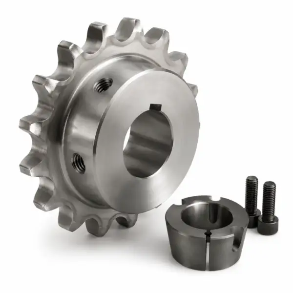
The bushing number defines taper and screw geometry as well as bore range. Do not substitute a QD or other split-taper bushing even when the shaft bore appears similar. The practical check for taper-lock is a specific bushing system is to connect the observed condition to Taper-Lock sprocket, then confirm that bushing installation does not introduce a second compatibility limit. For component context, review Taper-Lock sprockets when the linked product family is relevant to the same chain-drive interface.
For procurement, express taper-lock is a specific bushing system as verifiable data: chain standard, measured dimension, drawing reference, material condition, or operating requirement. Do not specify only ‘same as old.’
2. Shaft and bore condition matter
Raised fretting, rolled keyway edges, rust, and damaged keys can prevent full seating or create high local contact stress. Repair the shaft before fitting a new bushing. Record the evidence for shaft and bore condition matter beside the measured taper bushing. If keyway is size- or supplier-dependent, carry the drawing reference into the purchase record.
For commissioning, define how shaft and bore condition matter will be checked after installation: chain seating, runout, shaft clearance, tooth-side contact, rpm, or loaded inspection as applicable.
3. Use the designated mounting holes
Taper-Lock bushings use threaded and clearance holes for mounting and removal. Follow the product instructions so screw force draws the taper correctly rather than distorting the hub. Treat use the designated mounting holes as a pass/fail interface: document bushing installation, inspect the mating component, and use sprocket runout to confirm the final operating fit. For component context, review roller chain drive systems when the linked product family is relevant to the same chain-drive interface.
Verification for installing a taper-lock sprocket: compare the field condition with nominal data and treat any difference that changes roller seating, shaft support, or service access as a release criterion.
4. Do not invent tightening values
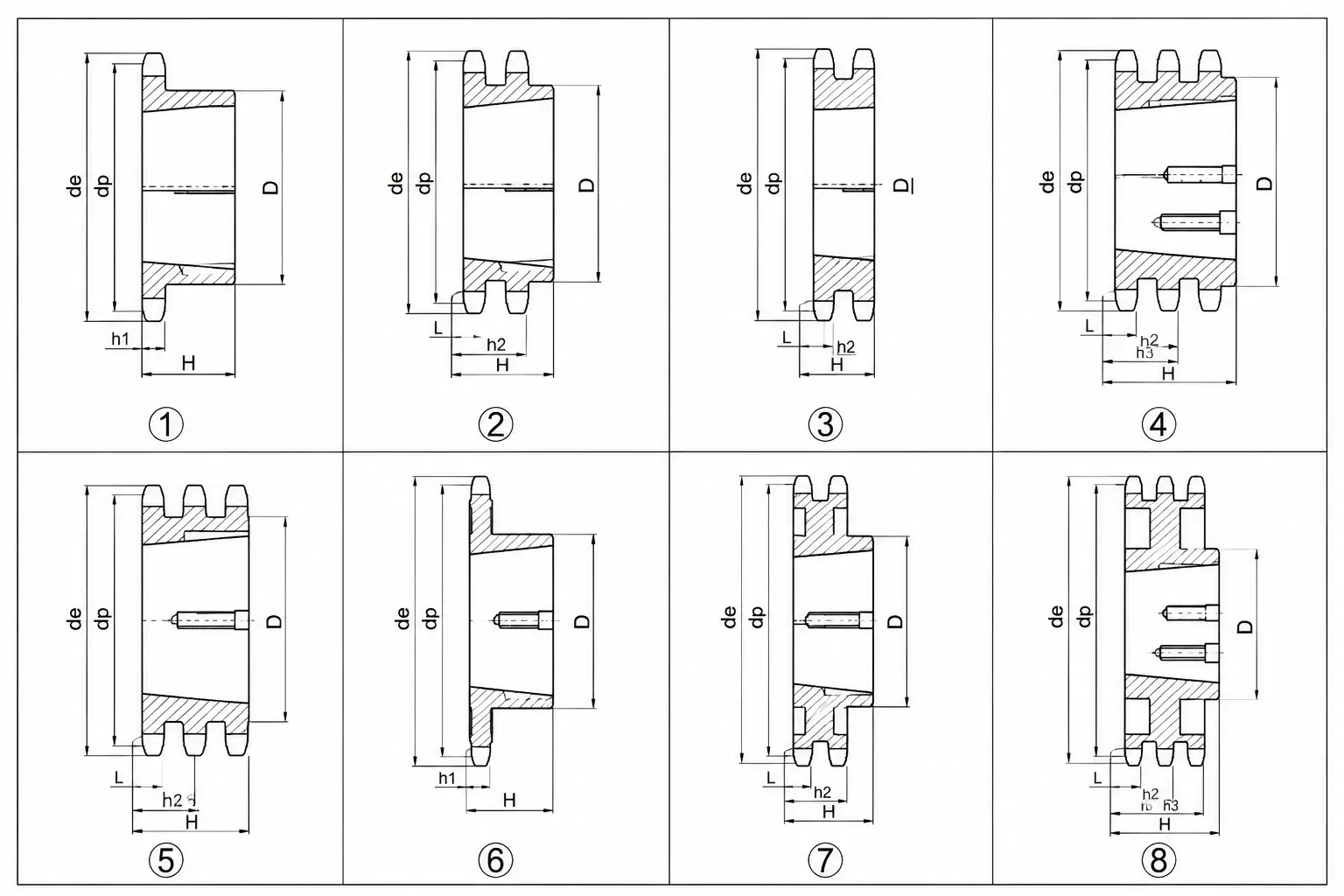
Screw size and bushing series determine the specified torque. Use current manufacturer data and tighten progressively in the prescribed pattern. A useful field note for installing a taper-lock sprocket pairs keyway with removal holes. That keeps the decision tied to the actual chain drive rather than a visual match.
Use the wear evidence to test do not invent tightening values: asymmetric polishing, fretting, root impact, or chain climbing should lead to a measurable correction rather than a like-for-like replacement.
5. Verify the sprocket after the taper is seated
Check chain-line position, radial runout, face wobble, key condition, and clearance to bearings or guards before installing the chain. For installing a taper-lock sprocket, use sprocket runout as the primary field reference and compare it with Taper-Lock sprocket; resolve any disagreement before releasing the sprocket specification.
For procurement, express verify the sprocket after the taper is seated as verifiable data: chain standard, measured dimension, drawing reference, material condition, or operating requirement. Do not specify only ‘same as old.’
Installation Check Matrix
| Factor | What to verify | Release logic |
|---|---|---|
| Taper-Lock is a specific bushing system | The bushing number defines taper and screw geometry as well as bore range | Reconstruct nominal taper-lock is a specific bushing system if wear has obscured the original geometry. |
| Shaft and bore condition matter | Raised fretting, rolled keyway edges, rust, and damaged keys can prevent full seating or create high local contact stress | Use the current supplier or machine limit for model-specific shaft and bore condition matter. |
| Use the designated mounting holes | Taper-Lock bushings use threaded and clearance holes for mounting and removal | Record use the designated mounting holes as a release check before installation or restart. |
| Do not invent tightening values | Screw size and bushing series determine the specified torque | Correct the system cause linked to do not invent tightening values before fitting new hardware. |
| Verify the sprocket after the taper is seated | Check chain-line position, radial runout, face wobble, key condition, and clearance to bearings or guards before installing the chain | Accept verify the sprocket after the taper is seated when field evidence matches the controlled requirement. |
| Use measured machine data and the current chain/sprocket drawing for final acceptance; model-specific limits are not interchangeable. | ||
Installation Sequence
- 1. Confirm the bushing. Match sprocket hub, Taper-Lock bushing number, shaft bore, keyway, screw set, and hub orientation. Repeat or rotate the check when wear could bias keyway; the goal is nominal geometry, not one convenient reading.
- 2. Prepare contact surfaces. Clean the shaft, bore, taper, key, and screw holes and correct burrs, galling, or corrosion that could alter seating. Photograph the setup when useful and identify the reference surfaces used to establish sprocket runout.
- 3. Assemble for the required chain line. Insert the bushing and key as specified and position the sprocket so final pull-up will leave the tooth plane aligned. If the observation changes removal holes, stop and update the replacement specification before continuing.
- 4. Tighten by the published sequence. Bring screws up gradually and evenly to the exact manufacturer torque for the bushing series. Repeat or rotate the check when wear could bias Taper-Lock sprocket; the goal is nominal geometry, not one convenient reading.
- 5. Measure final condition. Check sprocket axial location, radial runout, axial face runout, and free rotation before chain installation. Photograph the setup when useful and identify the reference surfaces used to establish taper bushing.
- 6. Use removal holes for disassembly. When removal is required, transfer screws to the designated jack-out positions and release the taper without striking the tooth rim or shaft. If the observation changes bushing installation, stop and update the replacement specification before continuing.
For installing a taper-lock sprocket, cross-check adjacent drive interfaces with industrial bushing and hub components before releasing the installation or replacement record.
Startup Verification
Avoid 01
Using QD installation habits on a Taper-Lock bushing. Document the corrective requirement specifically for installing a taper-lock sprocket before the part is released.
Avoid 02
Driving the bushing onto a damaged or oversized key. Document the corrective requirement specifically for installing a taper-lock sprocket before the part is released.
Avoid 03
Pulling the sprocket into alignment with chain tension after the taper is locked. Document the corrective requirement specifically for installing a taper-lock sprocket before the part is released.
Avoid 04
Reusing a cracked, stretched, or badly galled bushing. Document the corrective requirement specifically for installing a taper-lock sprocket before the part is released.
Configuration cross-check: use this Taper-Lock sprocket options only to compare common construction terminology for installing a taper-lock sprocket; release the part from the actual chain, shaft, and controlled drawing.
FAQ: Installing a Taper-Lock sprocket — practical engineering questions
How do I install a Taper-Lock sprocket correctly?
Confirm the bushing and shaft size, clean all mating surfaces, place the key and bushing in the specified orientation, tighten the correct holes progressively to the manufacturer torque, and verify alignment and runout.
Are Taper-Lock and QD bushings the same?
No. Both use split tapers, but the hub geometry, screw arrangement, and bushing series differ. They should not be mixed.
Why does my Taper-Lock sprocket wobble after installation?
Possible causes include shaft runout, dirt or burrs on the taper, uneven screw tightening, a damaged bushing, hub distortion, or poor sprocket flatness. Measure shaft and sprocket runout separately.
Should a Taper-Lock bushing be flush with the sprocket hub?
Do not use flushness as the acceptance criterion unless the specific product drawing says so. Use the manufacturer's seating and tightening procedure.
How do I remove a seized Taper-Lock bushing?
Use the designated removal holes and screws, clean exposed threads, and follow the manufacturer procedure. Avoid heating or hammering unless the equipment manufacturer explicitly permits it.
What details are needed to order a Taper-Lock sprocket?
State chain size, tooth count, hub and bushing series, shaft bore and keyway, material, tooth treatment, axial chain line, shaft speed, duty, and any special runout or corrosion requirement.