Engineering Scope
Installation Snapshot: Fitting a finished-bore sprocket to a keyed shaft
Verify bore fit, key geometry, shaft shoulder, hub orientation, axial retention, and sprocket alignment before applying load to a finished-bore chain sprocket. This article concentrates on finished bore sprocket, keyed shaft, shaft fit, keyway, set screw, and axial retention as field-verifiable decision inputs.
For fitting a finished-bore sprocket to a keyed shaft, keep chain engagement, shaft mounting, operating duty, and maintainability in the same decision record; use the current drawing whenever an exact limit is model-specific.
Field Reference
- Chain/tooth interface
- Confirm finished bore sprocket, keyed shaft, and the mating chain dimensions before changing hardware.
- Shaft/hub interface
- Record shaft fit and mounting details that control concentricity, axial position, or load transfer.
- Operating duty
- Document speed, load, shock, starts/reversals, contamination, washdown, and maintenance access relevant to fitting a finished-bore sprocket to a keyed shaft.
- Verification record
- For fitting a finished-bore sprocket to a keyed shaft, keep measured values, nominal drawing values, wear observations, and the final replacement requirement distinct in the service record.
Decision Principle
Release fitting a finished-bore sprocket to a keyed shaft from measured interfaces, not appearance.
For fitting a finished-bore sprocket to a keyed shaft, check the chain interface, shaft connection, duty, and installed geometry as separate acceptance items, then reconcile them in the final specification.
1. Finished bore does not mean universal fit
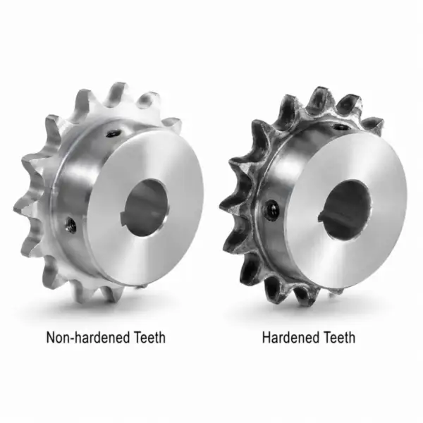
The nominal bore must match the actual shaft and intended fit. A worn, plated, repaired, or nonstandard shaft can differ enough to create looseness or assembly damage. A useful field note for fitting a finished-bore sprocket to a keyed shaft pairs finished bore sprocket with shaft fit. That keeps the decision tied to the actual chain drive rather than a visual match. For component context, review finished bore sprockets when the linked product family is relevant to the same chain-drive interface.
For commissioning, define how finished bore does not mean universal fit will be checked after installation: chain seating, runout, shaft clearance, tooth-side contact, rpm, or loaded inspection as applicable.
2. The key should fit both shaft and hub
Key width, height, and side fit determine how torque is transferred. A hammered or undersized key can allow movement that damages both keyways. For fitting a finished-bore sprocket to a keyed shaft, use keyed shaft as the primary field reference and compare it with keyway; resolve any disagreement before releasing the sprocket specification.
Verification for fitting a finished-bore sprocket to a keyed shaft: compare the field condition with nominal data and treat any difference that changes roller seating, shaft support, or service access as a release criterion.
3. Set screws and collars are retention details
Depending on the design, set screws may retain axial position or assist the key but should not be assumed to replace the intended torque-transmitting key or interference fit. The practical check for set screws and collars are retention details is to connect the observed condition to shaft fit, then confirm that set screw does not introduce a second compatibility limit. For component context, review industrial shaft mounting components when the linked product family is relevant to the same chain-drive interface.
Use the wear evidence to test set screws and collars are retention details: asymmetric polishing, fretting, root impact, or chain climbing should lead to a measurable correction rather than a like-for-like replacement.
4. Hub orientation controls chain plane
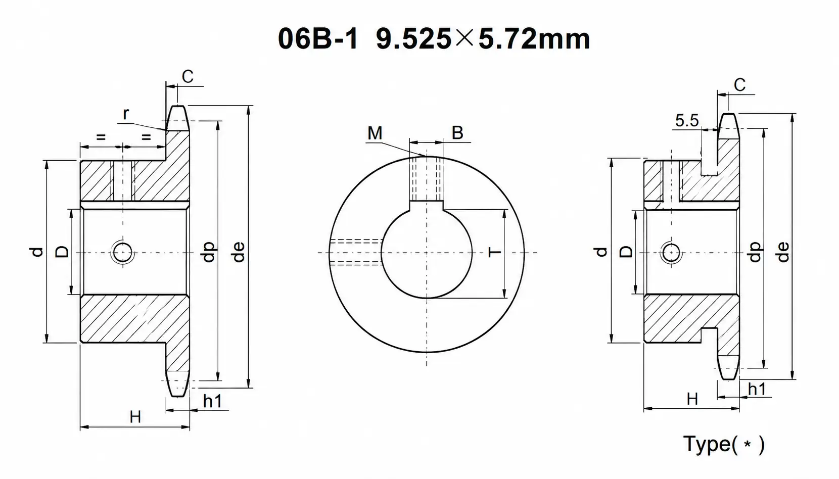
A finished-bore Type B sprocket can often be installed hub-in or hub-out, but only one orientation may place the tooth plane correctly and clear the bearing or guard. Record the evidence for hub orientation controls chain plane beside the measured keyway. If axial retention is size- or supplier-dependent, carry the drawing reference into the purchase record.
For procurement, express hub orientation controls chain plane as verifiable data: chain standard, measured dimension, drawing reference, material condition, or operating requirement. Do not specify only ‘same as old.’
5. Runout and alignment remain installation checks
Even a precision finished bore can wobble on a bent shaft, dirty shoulder, damaged key, or distorted sprocket. Verify after final assembly. Treat runout and alignment remain installation checks as a pass/fail interface: document set screw, inspect the mating component, and use finished bore sprocket to confirm the final operating fit.
For commissioning, define how runout and alignment remain installation checks will be checked after installation: chain seating, runout, shaft clearance, tooth-side contact, rpm, or loaded inspection as applicable.
Installation Sequence
- 1. Inspect the shaft. Measure shaft diameter, check straightness and bearing condition, clean the keyway and shoulder, and remove burrs or raised fretting material. Before moving on, confirm that keyway agrees with the mating chain or shaft interface relevant to this step.
- 2. Inspect the sprocket. Confirm finished bore, keyway, hub style, tooth count, chain size, and that the bore is clean and free from transport damage. Record the result against set screw so the next step starts from measured evidence.
- 3. Fit the key. Use the specified key size and length, checking that it seats without rocking or forcing the sprocket off center. Use the current machine drawing when axial retention is model-specific, and keep the measured value in the service record.
- 4. Install to the axial datum. Slide or press the sprocket using the approved fit method and locate the tooth plane relative to the machine or mating sprocket. Before moving on, confirm that finished bore sprocket agrees with the mating chain or shaft interface relevant to this step.
- 5. Secure axial retention. Install set screws, collars, nuts, or other retention using the machine drawing and model-specific torque data. Record the result against keyed shaft so the next step starts from measured evidence.
- 6. Check runout and chain tracking. Measure radial and axial runout, align the sprocket pair, install the chain, set slack, lubricate, and observe tracking during startup. Use the current machine drawing when shaft fit is model-specific, and keep the measured value in the service record.
For fitting a finished-bore sprocket to a keyed shaft, cross-check adjacent drive interfaces with roller chain drive components before releasing the installation or replacement record.
Installation Check Matrix
| Factor | What to verify | Release logic |
|---|---|---|
| Finished bore does not mean universal fit | The nominal bore must match the actual shaft and intended fit | Use the current supplier or machine limit for model-specific finished bore does not mean universal fit. |
| The key should fit both shaft and hub | Key width, height, and side fit determine how torque is transferred | Record the key should fit both shaft and hub as a release check before installation or restart. |
| Set screws and collars are retention details | Depending on the design, set screws may retain axial position or assist the key but should not be assumed to replace the intended torque-transmitting key or interference fit | Correct the system cause linked to set screws and collars are retention details before fitting new hardware. |
| Hub orientation controls chain plane | A finished-bore Type B sprocket can often be installed hub-in or hub-out, but only one orientation may place the tooth plane correctly and clear the bearing or guard | Accept hub orientation controls chain plane when field evidence matches the controlled requirement. |
| Runout and alignment remain installation checks | Even a precision finished bore can wobble on a bent shaft, dirty shoulder, damaged key, or distorted sprocket | Reconstruct nominal runout and alignment remain installation checks if wear has obscured the original geometry. |
| Use measured machine data and the current chain/sprocket drawing for final acceptance; model-specific limits are not interchangeable. | ||
Startup Verification
Avoid 01
Forcing a close bore onto a burred shaft with a hammer. Document the corrective requirement specifically for fitting a finished-bore sprocket to a keyed shaft before the part is released.
Avoid 02
Using a damaged key to make a loose keyway feel tight. Document the corrective requirement specifically for fitting a finished-bore sprocket to a keyed shaft before the part is released.
Avoid 03
Facing the hub the wrong way and shifting the chain line. Document the corrective requirement specifically for fitting a finished-bore sprocket to a keyed shaft before the part is released.
Avoid 04
Using set-screw torque from memory rather than the machine or sprocket data. Document the corrective requirement specifically for fitting a finished-bore sprocket to a keyed shaft before the part is released.
Configuration cross-check: use this finished bore sprocket options only to compare common construction terminology for fitting a finished-bore sprocket to a keyed shaft; release the part from the actual chain, shaft, and controlled drawing.
FAQ: Fitting a finished-bore sprocket to a keyed shaft — practical engineering questions
How tight should a finished-bore sprocket fit on the shaft?
Use the shaft and sprocket drawing or applicable fit standard. The required fit depends on shaft size, load, hub design, assembly method, and whether the key carries torque.
Can I reuse the old sprocket key?
Reuse only if it matches the specified size and shows no peening, fretting, distortion, or excessive side clearance. Keys are inexpensive compared with repairing damaged shaft and hub keyways.
Which way should the hub face on a finished-bore sprocket?
Orient it so the tooth plane aligns with the mating sprocket while the hub clears bearings, shoulders, guards, and service tools. Confirm axial position before final retention.
Do set screws transmit sprocket torque?
The design determines their role. On many keyed sprockets the key is the primary torque path and set screws provide retention or anti-movement. Follow the specific drawing rather than assuming a universal arrangement.
Why is a finished-bore sprocket loose on a nominally correct shaft?
Possible causes include shaft wear, bore wear, wrong nominal size, plating removal, keyway damage, or a fit different from the original design. Measure both parts at multiple locations.
What should I check after mounting a finished-bore sprocket?
Check axial location, key seating, retention hardware, radial and axial runout, sprocket alignment, chain slack, lubrication, and tracking during low-speed startup.