Engineering Scope
Selection Snapshot: Building a sprocket replacement specification sheet
Turn field measurements, chain identification, shaft data, duty, material, wear evidence, and dimensional references into a procurement document that avoids visual-match ordering errors. This article concentrates on sprocket specification sheet, replacement sprocket, chain size, bore and keyway, hub dimensions, and operating duty as field-verifiable decision inputs.
For building a sprocket replacement specification sheet, keep chain engagement, shaft mounting, operating duty, and maintainability in the same decision record; use the current drawing whenever an exact limit is model-specific.
Field Reference
- Chain/tooth interface
- Confirm sprocket specification sheet, replacement sprocket, and the mating chain dimensions before changing hardware.
- Shaft/hub interface
- Record chain size and mounting details that control concentricity, axial position, or load transfer.
- Operating duty
- Document speed, load, shock, starts/reversals, contamination, washdown, and maintenance access relevant to building a sprocket replacement specification sheet.
- Verification record
- For building a sprocket replacement specification sheet, keep measured values, nominal drawing values, wear observations, and the final replacement requirement distinct in the service record.
Decision Principle
Release building a sprocket replacement specification sheet from measured interfaces, not appearance.
For building a sprocket replacement specification sheet, check the chain interface, shaft connection, duty, and installed geometry as separate acceptance items, then reconcile them in the final specification.
Selection Procedure
- 1. Identify the drive position. Assign a machine tag, shaft name, driver or driven role, rotation direction, and photo reference so the part cannot be confused with a nearby sprocket. Before moving on, confirm that bore and keyway agrees with the mating chain or shaft interface relevant to this step.
- 2. Record chain data. State chain standard or number, pitch, roller diameter, inner width, strand count, and condition. Record the result against hub dimensions so the next step starts from measured evidence.
- 3. Record tooth and diameter data. Count teeth and record the drawing-controlled pitch, outside, caliper, or root dimensions used for identification. Use the current machine drawing when operating duty is model-specific, and keep the measured value in the service record.
- 4. Record shaft and hub data. Measure bore, keyway, bushing series, hub diameter, length through bore, tooth-plane offset, and available axial space. Before moving on, confirm that sprocket specification sheet agrees with the mating chain or shaft interface relevant to this step.
- 5. Record duty and environment. Add rpm, load or power, shock, starts, reversals, temperature, contamination, washdown, lubricant restrictions, and maintenance access. Record the result against replacement sprocket so the next step starts from measured evidence.
- 6. Define acceptance checks. State the drawing revision, material/heat treatment, critical dimensions, runout reference, marking, and any documentation that must accompany the replacement. Use the current machine drawing when chain size is model-specific, and keep the measured value in the service record.
For building a sprocket replacement specification sheet, cross-check adjacent drive interfaces with roller chain drive components before releasing the installation or replacement record.
1. Separate functional interfaces into blocks
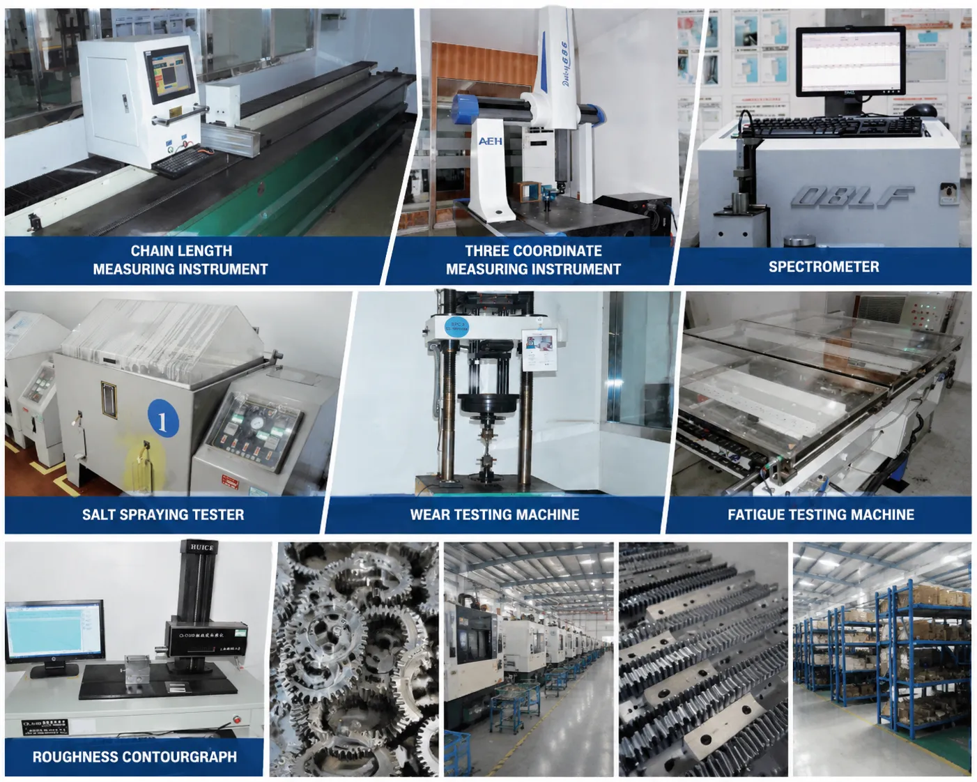
A useful sheet has dedicated fields for chain interface, tooth geometry, shaft interface, hub envelope, material, heat treatment, operating duty, and inspection requirements. The practical check for separate functional interfaces into blocks is to connect the observed condition to sprocket specification sheet, then confirm that chain size does not introduce a second compatibility limit. For component context, review replacement sprocket specifications when the linked product family is relevant to the same chain-drive interface.
Use the wear evidence to test separate functional interfaces into blocks: asymmetric polishing, fretting, root impact, or chain climbing should lead to a measurable correction rather than a like-for-like replacement.
2. Distinguish measured values from required values
A worn part may no longer represent the design. Record what was measured, what was found on a drawing, and what is required for the replacement as separate entries. Record the evidence for distinguish measured values from required values beside the measured replacement sprocket. If bore and keyway is size- or supplier-dependent, carry the drawing reference into the purchase record.
For procurement, express distinguish measured values from required values as verifiable data: chain standard, measured dimension, drawing reference, material condition, or operating requirement. Do not specify only ‘same as old.’
3. Include operating data
Shaft rpm, power or chain pull, shock, reversing, contamination, washdown, duty cycle, and maintenance access explain why material, tooth hardening, or bushing choices were made. Treat include operating data as a pass/fail interface: document chain size, inspect the mating component, and use hub dimensions to confirm the final operating fit. For component context, review industrial power transmission parts when the linked product family is relevant to the same chain-drive interface.
For commissioning, define how include operating data will be checked after installation: chain seating, runout, shaft clearance, tooth-side contact, rpm, or loaded inspection as applicable.
4. Use photos and datums
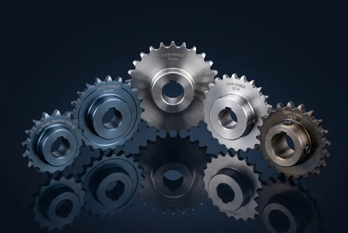
Photographs should show tooth wear, hub faces, keyway, chain markings, and machine clearances. Dimensions should reference named faces or shaft shoulders so another person can reproduce them. A useful field note for building a sprocket replacement specification sheet pairs bore and keyway with operating duty. That keeps the decision tied to the actual chain drive rather than a visual match.
Verification for building a sprocket replacement specification sheet: compare the field condition with nominal data and treat any difference that changes roller seating, shaft support, or service access as a release criterion.
5. Add an acceptance section
The receiving inspection should know what to check: chain series, tooth count, bore, keyway, hub dimensions, material, marking, and any runout or balance requirement stated on the drawing. For building a sprocket replacement specification sheet, use hub dimensions as the primary field reference and compare it with sprocket specification sheet; resolve any disagreement before releasing the sprocket specification.
Use the wear evidence to test add an acceptance section: asymmetric polishing, fretting, root impact, or chain climbing should lead to a measurable correction rather than a like-for-like replacement.
Decision Matrix
| Factor | What to verify | Release logic |
|---|---|---|
| Separate functional interfaces into blocks | A useful sheet has dedicated fields for chain interface, tooth geometry, shaft interface, hub envelope, material, heat treatment, operating duty, and inspection requirements | Reconstruct nominal separate functional interfaces into blocks if wear has obscured the original geometry. |
| Distinguish measured values from required values | A worn part may no longer represent the design | Use the current supplier or machine limit for model-specific distinguish measured values from required values. |
| Include operating data | Shaft rpm, power or chain pull, shock, reversing, contamination, washdown, duty cycle, and maintenance access explain why material, tooth hardening, or bushing choices were made | Record include operating data as a release check before installation or restart. |
| Use photos and datums | Photographs should show tooth wear, hub faces, keyway, chain markings, and machine clearances | Correct the system cause linked to use photos and datums before fitting new hardware. |
| Add an acceptance section | The receiving inspection should know what to check: chain series, tooth count, bore, keyway, hub dimensions, material, marking, and any runout or balance requirement stated on the drawing | Accept add an acceptance section when field evidence matches the controlled requirement. |
| Use measured machine data and the current chain/sprocket drawing for final acceptance; model-specific limits are not interchangeable. | ||
Final Verification
Avoid 01
Copying only the worn part dimensions with no original-drawing cross-check. Document the corrective requirement specifically for building a sprocket replacement specification sheet before the part is released.
Avoid 02
Leaving “material: steel” without grade or approved range when wear treatment matters. Document the corrective requirement specifically for building a sprocket replacement specification sheet before the part is released.
Avoid 03
Omitting the machine position and mixing similar sprockets in purchasing. Document the corrective requirement specifically for building a sprocket replacement specification sheet before the part is released.
Avoid 04
Using photos without scale or dimensional datums. Document the corrective requirement specifically for building a sprocket replacement specification sheet before the part is released.
Configuration cross-check: use this sprocket identification and ordering guide only to compare common construction terminology for building a sprocket replacement specification sheet; release the part from the actual chain, shaft, and controlled drawing.
FAQ: Building a sprocket replacement specification sheet — practical engineering questions
What should be included on a sprocket replacement specification sheet?
Include machine position, chain series and dimensions, tooth count, bore and keyway, hub dimensions, tooth-row location, material and heat treatment, operating duty, environment, and inspection requirements.
How do I specify a sprocket when the original drawing is missing?
Build the record from chain measurements, tooth count, hub and bore measurements, operating data, and unworn reference geometry. Flag worn dimensions and ask the supplier to verify the tooth form.
Should I include chain condition on a sprocket specification?
Yes. Chain elongation and wear help explain tooth damage and whether the new sprocket will be installed with a new or existing chain.
What photos are useful for a sprocket replacement quote?
Include full side view, hub and bore, keyway, chain marking, tooth close-ups, wear pattern, shaft location, nearby clearance, and a scale or known dimension.
How do I prevent the wrong bore or hub from being ordered?
Use a dimensional sketch with bore, keyway, hub diameter, length through bore, tooth-plane offset, and shaft shoulder reference instead of relying on a model description alone.
What receiving inspection should be done on a replacement sprocket?
Verify part marking, chain series, tooth count, bore/keyway or bushing, critical hub dimensions, material documentation where required, visible tooth condition, and runout if the application needs controlled precision.