Chain Drives for Reversing and Shock-Loaded Machinery: Selection and Design Considerations is best treated as an engineering judgement, not a part-number search. The equipment train first establishes function and duty; the chain and mating hardware then have to satisfy geometry, environment, and service constraints.
Identify the highest transient torque from starts, jams, impacts, and direction changes instead of using only average motor power in the selection process. Then reversal swaps the tight and slack sides, so chain guides, tensioners, and catenary assumptions must work in both directions rather than only for one normal running direction. Those two checks define why shock load and reversing drive belong in the same specification rather than being collected by separate teams after an order is placed.
For chain drives reversing shock-loaded, any numeric limit tied to slack-side reversal or fatigue must come from the applicable chain-series or equipment documentation; the sections below focus on how to obtain and interpret the engineering inputs.
- 주요 결정
- Size and arrange chain drives for reversals and shock by accounting for transient torque, slack-side reversal, sprocket engagement, fatigue, and tension control
- 첫 번째 증거
- 충격 하중
- 결합 인터페이스
- service factor
- 릴리스 체크
- fatigue reconciled with the selected product and machine data.
Confirm shock load, service factor, and the mating geometry first; a failure here eliminates the candidate regardless of price.
Then compare reversing drive, slack-side reversal, and fatigue with duty, environment, and service access before release.
1. Map the Machine Duty
Identify the highest transient torque from starts, jams, impacts, and direction changes instead of using only average motor power in the selection process
For chain drives reversing shock-loaded, build shock load from the duty cycle rather than a single nameplate number. Separate steady resistance from starts, stops, jams, acceleration, reversals, lifted mass, and impact, then set beside the resulting demand with reversing drive using the specified manufacturer rating method. With chain drives reversing shock-loaded duty fixed, review the industrial roller chain 이 인터페이스와 일치하는 옵션입니다.
2. Follow the Load Through the Operating Cycle
Reversal swaps the tight and slack sides, so chain guides, tensioners, and catenary assumptions must work in both directions rather than only for one normal running direction
For chain drives reversing shock-loaded, load direction and slack behavior can change within a cycle. A reversal may swap tight and slack spans, while impact can move hubs or tensioners. Interpret reversing drive alongside slack-side reversal so the chain, bearings, keys, and sprockets are checked as one load path.
| 확인하다 | 공학적 중요성 | 검증 접근법 |
|---|---|---|
| Shock Load | identify the highest transient torque from starts, jams, impacts, and direction changes instead of using only average motor power in the selection process | Verify shock load from a named datum or approved source, then reconcile reversing drive for chain drives reversing shock-loaded in advance of release. |
| Reversing Drive | reversal swaps the tight and slack sides, so chain guides, tensioners, and catenary assumptions must work in both directions rather than only for one normal running direction | Verify reversing drive from a named datum or approved source, then reconcile service factor for chain drives reversing shock-loaded before release. |
| Service Factor | use the manufacturer service-factor and power-rating method for the actual prime mover and machine class; minimum tensile strength is not a substitute for fatigue-based drive selection | Verify service factor from a named datum or approved source, then reconcile slack-side reversal for chain drives reversing shock-loaded before release. |
| Slack-Side Reversal | avoid unnecessarily small sprockets because high articulation and tooth loading can aggravate impact, vibration, and polygonal action during rapid reversals | Verify slack-side reversal from a named datum or approved source, then reconcile fatigue for chain drives reversing shock-loaded prior to release. |
| 릴리스 게이트 | Approve chain drives reversing shock-loaded only after field evidence, mating geometry, and the selected chain data agree. | |
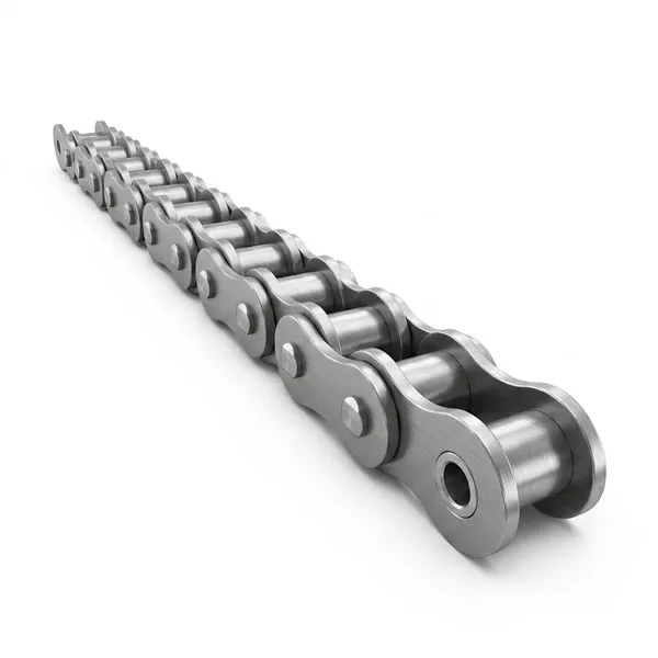
3. Choose the Chain Architecture and Interfaces
Use the manufacturer service-factor and power-rating method for the actual prime mover and machine class; minimum tensile strength is not a substitute for fatigue-based drive selection
Document service factor for chain drives reversing shock-loaded as a time history: what the chain carries, how it accelerates, whether slack is taken up suddenly, and how often the event repeats. Review slack-side reversal against the same case so capacity, fatigue, and mating-assembly loads are evaluated together. For chain drives reversing shock-loaded, use the chain sprocket dimensions range only after service factor passes the machine check.
For chain drives reversing shock-loaded, separate “fits” from “is suitable.” service factor can establish geometry while fatigue establishes duty or observed state. Approve the service replacement only when the two agree and the proposed equipment maker specification supports the operating case; otherwise document the unresolved item rather than masking it with extra tension or oversizing.
4. Design for the Real Environment
Avoid unnecessarily small sprockets because high articulation and tooth loading can aggravate impact, vibration, and polygonal action during rapid reversals
Engagement quality is central to chain drives reversing shock-loaded. A pitch-correct chain can still side-load when sprocket faces are offset, shafts are not parallel, or tooth wear shifts contact. Read slack-side reversal together with shock load; the wear pattern often reveals whether the error is constant or varies once per revolution. A supplementary industrial chain types can be reviewed after slack-side reversal is fixed.
Send shock load, service factor, the mating-component condition, duty, and photographs of the measured references so the open interface can be reviewed before ordering.
5. Protect Serviceability and Alignment
Check shaft keys, hubs, bearings, and mount stiffness as part of the load path because a shock event can move a sprocket or create misalignment even when the chain itself remains intact
On chain drives reversing shock-loaded, fatigue is credible only when the load case is named. Log normal running, peak or upset conditions, frequency of transients, and the speed at which they occur; pair those observations with shock load. Do not substitute minimum tensile strength for an allowable working or fatigue selection method. Procurement for chain drives reversing shock-loaded can use the industrial transmission solutions category after shock load is reconciled.
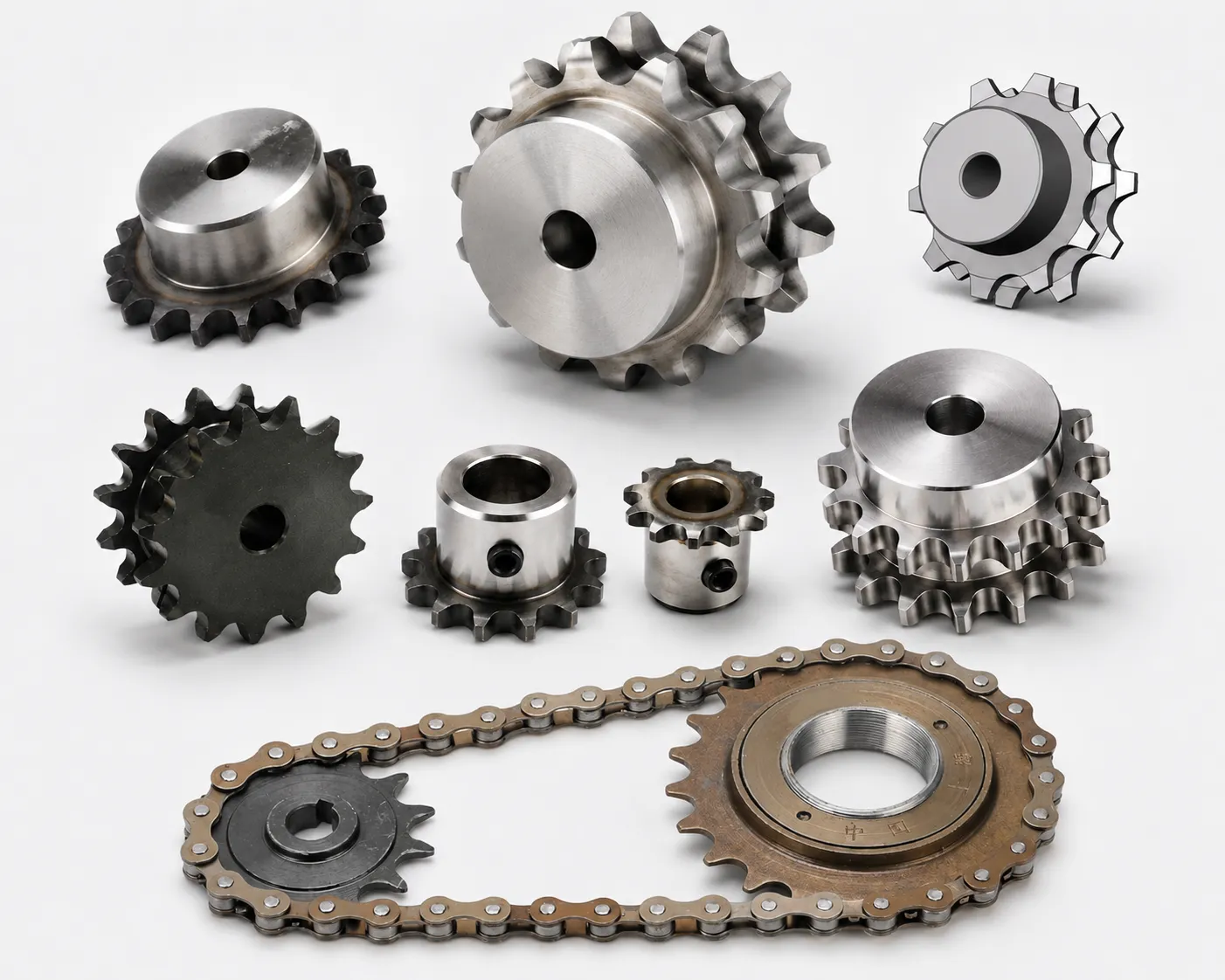
6. Verify the Application Before Release
After commissioning, inspect connecting links, plate holes, pins, tooth contact, and tensioner travel after representative reversals so early impact damage is found before it propagates
The mating geometry in chain drives reversing shock-loaded converts shaft position into chain load. Runout creates cyclic tension, lateral offset pushes plates sideways, and worn tooth roots distort seating. Comparing shock load with service factor helps identify which interface is producing the visible symptom.
Field Example: Turning Chain Drives Reversing Shock-loaded Into a Release Decision
A buyer and technician can make chain drives reversing shock-loaded auditable by walking the equipment together before the request for quotation is issued. Identify the highest transient torque from starts, jams, impacts, and direction changes instead of using only average motor power in the selection process. Next, the team checks reversing drive and service factor while the relevant mating hardware is exposed. The sequence matters: it establishes function and geometry before a catalogue size is allowed to influence the release choice.
The service-side review then applies two different questions. First, avoid unnecessarily small sprockets because high articulation and tooth loading can aggravate impact, vibration, and polygonal action during rapid reversals. Second, review shaft keys, hubs, bearings, and mount stiffness as part of the load path because a shock event can move a sprocket or create misalignment even when the chain itself remains intact. The team records slack-side reversal with the environment and maintenance access instead of treating it as a later service issue. That makes the specification usable by both procurement and maintenance.
Release follows only after after commissioning, assess connecting links, plate holes, pins, tooth contact, and tensioner travel after representative reversals so early impact damage is found prior to it propagates. The chain drives reversing shock-loaded work order keeps shock load, service factor, fatigue, interface photographs, and the governing document used for any series-specific limit.
Chain Drives Reversing Shock-loaded Release Checklist
- Identify the highest transient torque from starts, jams, impacts, and direction changes instead of using only average motor power in the selection process. Document the evidence for shock load with a named reference.
- Reversal swaps the tight and slack sides, so chain guides, tensioners, and catenary assumptions must work in both directions rather than only for one normal running direction. Keep the reversing drive observation with the chain drives reversing shock-loaded work order.
- Use the equipment maker service-factor and power-rating method for the actual prime mover and installation class; minimum tensile strength is not a substitute for fatigue-based drive selection. Use the applicable product criterion when service factor needs a numeric limit.
- Avoid unnecessarily small sprockets because high articulation and tooth loading can aggravate impact, vibration, and polygonal action during rapid reversals. Reconcile slack-side reversal with the mating hardware prior to release.
- Examine shaft keys, hubs, bearings, and mount stiffness as part of the load path because a shock event can move a sprocket or create misalignment even when the chain itself remains intact. Repeat the fatigue examine where position or wear can change the result.
- Once commissioning, review connecting links, plate holes, pins, tooth contact, and tensioner travel once representative reversals so early impact damage is found before it propagates. Archive shock load with the chain identity and drive duty.
Chain Drives Reversing Shock-loaded FAQ
How do I choose or verify shock load for chain drives reversing shock-loaded?
For chain drives reversing shock-loaded, the first verify is shock load. Identify the highest transient torque from starts, jams, impacts, and direction changes instead of using only average motor power in the selection process. If a numeric limit is needed for service factor, use the exact equipment or chain-series criterion.
What machine data is needed before checking reversing drive?
With chain drives reversing shock-loaded, judge reversing drive in its real service state. Reversal swaps the tight and slack sides, so chain guides, tensioners, and catenary assumptions must work in both directions rather than only for one normal running direction. If the reversing drive evidence conflicts with slack-side reversal, resolve the interface before purchasing the replacement.
How do I know whether service factor is compatible with the existing system?
For this chain drives reversing shock-loaded question, verify service factor and fatigue together. Use the equipment maker service-factor and power-rating method for the actual prime mover and installation class; minimum tensile strength is not a substitute for fatigue-based drive selection. Keep the service factor reading with the maintenance preserve so future inspections can trend change.
Can I select a replacement by slack-side reversal alone?
On chain drives reversing shock-loaded, appearance alone cannot establish slack-side reversal. Avoid unnecessarily small sprockets because high articulation and tooth loading can aggravate impact, vibration, and polygonal action during rapid reversals. After correction, recheck shock load under the same permitted service working state used to corroborate the symptom.
When does fatigue become the limiting factor for chain drives reversing shock-loaded?
A defensible chain drives reversing shock-loaded answer begins with measured fatigue. Examine shaft keys, hubs, bearings, and mount stiffness as part of the load path because a shock event can move a sprocket or create misalignment even when the chain itself remains intact. For lifting or other safety-critical duty, the equipment-specific inspection and release method governs.
What should be documented before releasing a chain drives reversing shock-loaded replacement order?
Before releasing chain drives reversing shock-loaded, document shock load and service factor. Once commissioning, review connecting links, plate holes, pins, tooth contact, and tensioner travel once representative reversals so early impact damage is found before it propagates. Include the mating sprocket, sheave, guide, or attachment whenever service factor is part of the load path.
Cxm.