エンジニアリングの範囲
Selection Snapshot: Split sprockets and solid sprockets
Compare downtime, shaft access, concentricity, structural stiffness, fastening, and replacement frequency before choosing a split or one-piece sprocket. This article concentrates on split sprocket, solid sprocket, segmental sprocket, maintenance downtime, concentricity, and shaft access as field-verifiable decision inputs.
For split sprockets and solid sprockets, keep chain engagement, shaft mounting, operating duty, and maintainability in the same decision record; use the current drawing whenever an exact limit is model-specific.
フィールドリファレンス
- チェーン/歯面
- Confirm split sprocket, solid sprocket, and the mating chain dimensions before changing hardware.
- シャフト/ハブインターフェース
- Record segmental sprocket and mounting details that control concentricity, axial position, or load transfer.
- 運用上の義務
- Document speed, load, shock, starts/reversals, contamination, washdown, and maintenance access relevant to split sprockets and solid sprockets.
- 検証記録
- For split sprockets and solid sprockets, keep measured values, nominal drawing values, wear observations, and the final replacement requirement distinct in the service record.
意思決定の原則
Release split sprockets and solid sprockets from measured interfaces, not appearance.
For split sprockets and solid sprockets, check the chain interface, shaft connection, duty, and installed geometry as separate acceptance items, then reconcile them in the final specification.
1. Split designs reduce disassembly
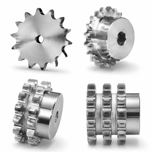
A split sprocket can be installed around a shaft when bearings, couplings, or large machine structures make axial removal difficult. The main value is maintenance access, not an inherent increase in power capacity. Treat split designs reduce disassembly as a pass/fail interface: document split sprocket, inspect the mating component, and use segmental sprocket to confirm the final operating fit. For component context, review split and solid sprocket designs リンクされた製品ファミリーが同じチェーン駆動インターフェースに関連している場合。
For procurement, express split designs reduce disassembly as verifiable data: chain standard, measured dimension, drawing reference, material condition, or operating requirement. Do not specify only ‘same as old.’
2. Joint accuracy controls runout
The split faces, pilots, bolts, keys, and any dowels must locate the halves accurately. Dirt or burrs at the joint can create radial runout, axial wobble, or tooth-spacing error at the split. A useful field note for split sprockets and solid sprockets pairs solid sprocket with maintenance downtime. That keeps the decision tied to the actual chain drive rather than a visual match.
For commissioning, define how joint accuracy controls runout will be checked after installation: chain seating, runout, shaft clearance, tooth-side contact, rpm, or loaded inspection as applicable.
3. Solid sprockets maximize geometric simplicity
A one-piece sprocket removes the split joint and can simplify concentric machining. It is attractive where the shaft can be accessed easily and replacement downtime is not dominated by bearing or coupling removal. For split sprockets and solid sprockets, use segmental sprocket as the primary field reference and compare it with concentricity; resolve any disagreement before releasing the sprocket specification. For component context, review engineering chains and sprockets リンクされた製品ファミリーが同じチェーン駆動インターフェースに関連している場合。
Verification for split sprockets and solid sprockets: compare the field condition with nominal data and treat any difference that changes roller seating, shaft support, or service access as a release criterion.
4. Large conveyors may use replaceable segments
Segmental rims allow worn tooth sections to be changed while a central hub remains on the shaft. This is common in large or difficult-to-access conveyor drives where complete sprocket replacement would be costly. The practical check for large conveyors may use replaceable segments is to connect the observed condition to maintenance downtime, then confirm that shaft access does not introduce a second compatibility limit.
Use the wear evidence to test large conveyors may use replaceable segments: asymmetric polishing, fretting, root impact, or chain climbing should lead to a measurable correction rather than a like-for-like replacement.
5. Lifecycle cost is installation-specific
A split design can justify a higher part cost if it eliminates hours of machine disassembly. Conversely, a solid sprocket can be better when precision, stiffness, and low replacement frequency dominate. Record the evidence for lifecycle cost is installation-specific beside the measured concentricity. If split sprocket is size- or supplier-dependent, carry the drawing reference into the purchase record.
For procurement, express lifecycle cost is installation-specific as verifiable data: chain standard, measured dimension, drawing reference, material condition, or operating requirement. Do not specify only ‘same as old.’
比較マトリックス
| 要素 | 確認すべき事項 | リリースロジック |
|---|---|---|
| Split designs reduce disassembly | A split sprocket can be installed around a shaft when bearings, couplings, or large machine structures make axial removal difficult | Accept split designs reduce disassembly when field evidence matches the controlled requirement. |
| Joint accuracy controls runout | The split faces, pilots, bolts, keys, and any dowels must locate the halves accurately | Reconstruct nominal joint accuracy controls runout if wear has obscured the original geometry. |
| Solid sprockets maximize geometric simplicity | A one-piece sprocket removes the split joint and can simplify concentric machining | Use the current supplier or machine limit for model-specific solid sprockets maximize geometric simplicity. |
| Large conveyors may use replaceable segments | Segmental rims allow worn tooth sections to be changed while a central hub remains on the shaft | Record large conveyors may use replaceable segments as a release check before installation or restart. |
| Lifecycle cost is installation-specific | A split design can justify a higher part cost if it eliminates hours of machine disassembly | Correct the system cause linked to lifecycle cost is installation-specific before fitting new hardware. |
| 最終承認には、測定された機械データと最新のチェーン/スプロケット図面を使用してください。機種固有の制限値は互換性がありません。 | ||
選考手順
- 1. Map the disassembly path. List which bearings, couplings, guards, and shaft-mounted components must be removed to slide a solid sprocket off the shaft. Photograph the setup when useful and identify the reference surfaces used to establish maintenance downtime.
- 2. Inspect the shaft seat. Measure bore location, keyway, shaft condition, and available radial clearance for assembling split halves or segments. If the observation changes concentricity, stop and update the replacement specification before continuing.
- 3. Review joint hardware. Check the manufacturer's bolt, dowel, pilot, or clamping arrangement and confirm access for tightening and future removal. Repeat or rotate the check when wear could bias shaft access; the goal is nominal geometry, not one convenient reading.
- 4. Plan runout inspection. Choose indicator surfaces and acceptance limits from the drawing or machine specification, then check the assembled sprocket through a full revolution. Photograph the setup when useful and identify the reference surfaces used to establish split sprocket.
- 5. Estimate maintenance value. Compare expected replacement frequency and downtime saved with the additional inspection and assembly work of the split joint. If the observation changes solid sprocket, stop and update the replacement specification before continuing.
- 6. Control spares. Store matched split halves or segment sets together and mark their orientation so mixed components are not assembled during an outage. Repeat or rotate the check when wear could bias segmental sprocket; the goal is nominal geometry, not one convenient reading.
For split sprockets and solid sprockets, cross-check adjacent drive interfaces with 産業用動力伝達部品 インストールまたは交換記録を公開する前に。
最終選考チェック
01 を避ける
Treating a split sprocket as self-aligning. Document the corrective requirement specifically for split sprockets and solid sprockets before the part is released.
02を避ける
Assembling over rust, paint, or burrs on the split faces. Document the corrective requirement specifically for split sprockets and solid sprockets before the part is released.
03 は避けてください
Mixing halves from different matched sets. Document the corrective requirement specifically for split sprockets and solid sprockets before the part is released.
04を避ける
Choosing solid construction on a shaft that requires major bearing removal for every replacement. Document the corrective requirement specifically for split sprockets and solid sprockets before the part is released.
設定の相互チェック: これを使う カスタムスプロケット構成 only to compare common construction terminology for split sprockets and solid sprockets; release the part from the actual chain, shaft, and controlled drawing.
FAQ: Split sprockets and solid sprockets — practical engineering questions
Split sprocket vs solid sprocket: which is better?
A split sprocket is better when shaft access makes one-piece removal expensive; a solid sprocket is simpler when the shaft is easy to access and maximum geometric simplicity is preferred. Compare downtime, runout control, joint maintenance, and expected replacement frequency.
Can a split sprocket run as accurately as a solid sprocket?
It can when the joint, pilot, bore, and fastening system are accurately manufactured and assembled cleanly. Verify radial and axial runout after installation rather than assuming either construction is automatically more accurate.
When are segmental sprockets used on conveyors?
They are useful on large conveyor sprockets where the tooth rim wears but the hub and shaft connection remain serviceable. Replaceable segments can reduce outage time and material replaced.
Do split sprockets need special alignment?
They require the same shaft parallelism and tooth-plane alignment as solid sprockets plus inspection of the split joint itself. Check more than one rotational position to detect assembly error.
Can I convert a solid sprocket to a split sprocket?
Only through an engineered design that provides a reliable split joint, hub connection, fastening, and concentric location. Simply cutting a standard sprocket in half is not an acceptable conversion.
What data is needed for a custom split sprocket?
Provide chain type, tooth count, pitch, bore and shaft details, keyway, split orientation, joint and fastening preference, material, load, speed, environment, and the clearance available for assembly around the shaft.